How does the Flow Manager work?
In this page it will be explained how the Flow Manager works.
The finite state machine
As mentioned in the service introduction, the Flow Manager is based on a Finite State Machine.
More precisely it receives a finite state machine in a configuration file (in a section of it) and, thanks to it, can handle the Saga flow how described into the machine.
The Flow Manager is not capable to understand if a finite state machine is a valid one, if there are loops and so on, it just configures itself and follows the configured flow.
Every state of the machine can have its properties, for example:
- the command to send when the saga lands on the state and the channel to be used for it
- the expected events and, for each one, the destination state
- other details
Look at the machine definition configuration section for more technical details on how to configure your Finite State Machine.
Business states
The Flow Manager has the concept of Business States, useful to discern the internal states (of the Finite State Machine) to the states that matter for the business.
Each business state can contain one or more states of the machine.
"States that matter for the business" means that a business state represents a state of the Saga that is not "Intermediate", that symbolizes what is the whole saga status.
Let's explain it with an example based on the usual Finite State Machine (the businessStates are the numbers in each state):
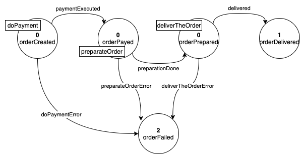
The image above contains all the internal states of the Saga, but not all states could be important for the business. For example, the business could care about:
- the order is created → 0
- the order is delivered → 1
- the order is failed → 2
When an order is delivered, the businessState will be 1, that means that the payment is done and the deliver too, the businessState 1 contains all the information that matters for the business.
In this way the users can look for successfully completed orders just by looking for the orders with businessState set to 1.
The one above is just a very simple example that just excludes one Finite State Machine state from the Business States, but in real scenarios the actual Business States can be less than half of the Finite State Machine ones.
The business states are a superset of the machine that represents the states of the saga that matter for its business.
Business events
Another key concept of the Flow Manager is the one of Business Events, a way of grouping the internal events into business relevant ones.
Each business event can be associated to one or more events.
The concept is explained in the following example based on the usual Finite State Machine (the businessEvents are the numbered ones):
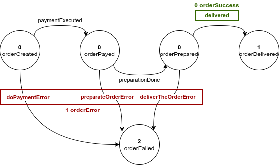
In the image above, the events belonging to the same business event are grouped by color. As shown, not all the internal events are important for the business. For example, paymentExecuted and preparationDone do not give any business relevant information, while delivered does since it sums the success of the whole project.
Commands events approach
In order to correctly handle the saga flow, the Flow Manager, needs the support of other actors, or, microservices that execute the tasks to move forward the saga.
To do this, the service uses the command/event approach, or:
- every time that the saga goes in a new state, the Flow Manager sends a command (if expected into the current state) through the specified channel
- another service listens the command, executes it and replies with a event into the expected channel
- the Flow Manager listens the event from the channel and, if is a expected event in the current state, goes to the next state, related to the event
If a command execution fails, an error event will be sent by the executor actor instead of the done event; in this case, the possible management of the error state is delegated to the user that writes the Flow Manager configurations file (to go, for example, in a error state with remediation actions).
If an unexpected event for the current state is received, the Flow Manager will just generate an error log and ignore the event.
Naming convention and best practices
Usually the following are the best practices for events and commands:
-
commands should be imperative, as:
- doPayment
- prepareOrder
- shipTheOrder
-
events should be to the past:
- paymentDone
- orderPreparated
-
error events should be like the command, with the Error suffix:
- doPaymentError
- prepareOrderError
Sample flows
Following some sample flow based on the following finite state machine, in which the rectangles indicate the commands of each state:
Happy flow
- Flow Manager:
- creates the saga (the order)
- moves the order in orderCreated state
- sends the doPayment command
- a Payment Service:
- successfully elaborates the payment
- sends the paymentExecuted event
- Flow Manager:
- listens the paymentExecuted event
- moves the order in orderPayed state
- sends the preparateOrder command
- ... and so on
Error flow
- Flow Manager:
- creates the saga (the order)
- moves the order in orderCreated state
- sends the doPayment command
- a Payment Service:
- listens the doPayment command
- successfully elaborates the payment
- sends the paymentExecuted event
- Flow Manager:
- listens the paymentExecuted event
- moves the order in orderPayed state
- sends the preparateOrder command
- a Preparation Service:
- listens the preparateOrder command
- throws a error during the order preparation
- sends the preparateOrderError event
- Flow Manager:
- listens the preparateOrderError event
- moves the order in orderFailed state
Flow with unexpected event
- Flow Manager:
- creates the saga (the order)
- moves the order in orderCreated state
- sends the doPayment command
- listens a preparationDone event
- logs an error for the unexpected event and ignores it
In this case the Flow Manager, while in orderCreated state, was expecting a paymentExecuted event to continue, like specified in the configurations file; it received the preparationDone event instead and, since this event was unexpected, the Flow Manager simply ignores it and logs an error.
Service metadata
The Flow Manager is a platform core service and this implies that it must be generic and configurable with each Saga flow.
To do this, it cannot know the nature of the data behind a saga, it cannot know if the Saga represents a Food delivery order, a e-commerce order or other.
For this reason the service is agnostic and does not know anything about the data related to the saga, but how can it handle it so?
It handles the saga data with the concept of metadata.
The metadata are all the data strictly related to the specific saga, different for each Saga flow, e.g:
-
the food delivery order metadata could contain:
- the list of ordered plates
- the total price
- the address
- ... and so on
-
the alarm reporting from IoT sensors in a house could contain instead:
- the alarm types
- the channels used to notify the user
- the alarms timestamps
- the current alarms states
- ... and so on
Saga data structure
The saga data is split, to allow the Flow Manager to be generic, in a static part and in a dynamic part.
The static part is the common Saga data, or, data that all sagas have:
- the Saga ID (generated by the Flow Manager when the saga is created)
- the current state of the saga
- an associated entity ID, that is the ID of the core entity related to the saga, e.g:
- for a Food Delivery order it could be the order ID
- for a Payment flow it could be the ID of the title to pay
- the business state ID (see business states)
- the business state description (see business states)
- the history of the saga (see saga history)
- the isFinal flag, that indicates if the current state is a final one
All the fields above are common fields of the saga and are not related to the specific case
Saga history
The history of the saga consists in the list of all the occurred states and events saved in chronological order. It has the following structure:
{
  "states": [
    {
      "state": "The name of the state",
      "timestamp": "The time at which the saga has moved in the state",
      "businessStateId": "The id of the associated business state",
      "businessStateDescription": "The description of the associated business state, if present"
    }
  ],
  "events": [
    {
      "event": "The name of the event",
      "timestamp": "The time at which the event occurred",
      "businessEventId": "The id of the associated business event, if present",
      "businessEventDescription": "The description of the associated business event, if present"
    }
  ]
}
Data persistency and consistency
The purpose of the Flow Manager is to guarantee data consistency.
To do this, the service should be the only one to manipulate the Saga's data and metadata.
Actually the service can be the only one to read the data too, because it makes sure to provide all metadata to other services.
Specifically the service does the following steps to ensure the data consistency:
-
when the Flow Manager sends a command, it puts into the command payload all the Saga's metadata, to allow the service that will handle the command to know all about the saga without read from the database
-
when the Flow Manager listens a event, it does the following actions:
- takes the metadata from the event payload (that should be only the new metadata, added during the command handling by the specific service)
- takes the current Saga's metadata from the database
- merges the current metadata with the new metadata (it is just a first level merge, nested objects will be completely substitute with the new ones):
{ name: 'Chester', surname: 'Bennington', address: { country: 'California' } }, merged with:{ name: 'Chester', surname: 'Bennington', age: 41, address: { zip: '12345' } }, will become:{ name: 'Chester', surname: 'Bennington', age: 41, address: { zip: '12345' } }.
- saves the merged metadata into the database
- if a command must be sent, it puts the merged metadata into the payload
With the behavior explained above, the Flow Manager can guarantee:
- to be the only one to edit the Saga's data
- to provide all metadata to the "side services" that will listen to the commands, so that the "side services" don't need to read it from the database
Obviously some other service could need to read from the Saga's database, it's not a problem, the important thing is that the Flow Manager should be the only one to write on it.
The persistency manager
To avoid any database coupling, the Flow Manager does not have a direct link any the database.
To perform read/write operations on data it requires another actor: the Persistency Manager (configurable in the configurations file).
The tasks of the Persistency Manager are to:
-
provide a method to upsert a saga by receiving all of its data
-
provide a method to get a saga, that must return:
- the current state
- the Saga's metadata
Interacting with the Flow Manager
The Flow Manager service exposes a POST route on /saga that allows to create new Sagas. It automatically stores the saga on your persistency manager, creates the id of the Saga, sends the creation command and returns the id.
It requires the following body:
{
  "type": "object",
  "properties": {
    "associatedEntityId": {
      "type": "string",
      "description": "The id of the entity associated to the saga",
    },
    "metadata": {
      "type": "object",
      "description": "The metadata associated to the saga",
      "additionalProperties": true,
    },
  },
  "required": ["associatedEntityId", "metadata"],
  "additionalProperties": false,
}